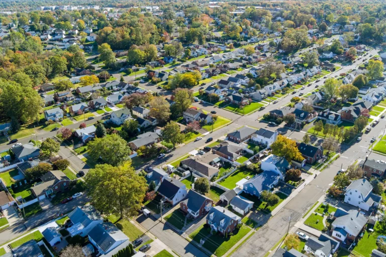
Accurate cooling capacity starts with a Manual J load calculation that quantifies every heat source inside a Sewell home. Solar gain through glass, conduction through walls and attic assemblies, infiltration driven by wind and stack effect, and internal loads from people, lighting, and appliances all add up to a specific number of British thermal units that must be removed each hour. We measure insulation R-values, window U-factors and solar heat-gain coefficients, air-change rates, and occupancy schedules rather than apply generic square-footage multipliers that routinely miss the mark by 15 to 25 percent. An undersized condenser and evaporator coil will run without pause yet never reach the thermostat set point on the hottest July afternoon. An oversized pair will satisfy the thermostat in minutes, shut off, and leave humidity high enough to feel clammy. W.B. Steward & Son performs the full ACCA Manual J procedure on every AC installation so the equipment we select matches the actual load of your house.
Capacity Determination Through Room-by-Room Analysis
We divide the home into individual zones and calculate the load for each space separately. A west-facing living room with large windows receives far more afternoon radiation than a north-facing bedroom with modest glazing. Kitchen heat from cooking and a second-floor bonus room under a dark roof each require their own numbers. The software we use incorporates local design temperatures for Gloucester County: 91 °F dry-bulb and 74 °F wet-bulb outdoor conditions together with 75 °F indoor dry-bulb and 50 percent relative humidity. Those values produce both a sensible load that lowers air temperature and a latent load that removes moisture. Only after the room-by-room totals are complete do we size the outdoor condensing unit and the indoor evaporator coil. Matching the two components to within a few hundred BTUh prevents the short-cycling that destroys compressors and the inadequate dehumidification that encourages mold growth on supply registers.
Duct leakage and insulation levels also enter the calculation. Many Sewell homes built before 2000 have unsealed attic ducts that lose 20 percent or more of the cooled air before it reaches the living space. We measure existing leakage with a duct blaster when the old system is still in place and add that extra load to the Manual J total. If the ducts cannot be sealed or replaced, we increase equipment capacity accordingly. The finished report lists every assumption so you can see exactly why a 2.5-ton or 3-ton system is the correct choice. Free estimates include this documented load calculation at no extra charge, and financing options are available if you decide to proceed.
Matching Bryant Equipment to Calculated Loads and Efficiency Targets
Once the load is known we select from the Bryant product line as a Factory Authorized Dealer. Current federal minimums require 14.3 SEER2 for split systems in the northern region that includes New Jersey, yet we routinely install 16-SEER2 and 18-SEER2 models because the extra efficiency pays back through lower summer electric bills and quieter operation. The outdoor unit must also satisfy the sensible-heat ratio demanded by our humid climate; a coil with too little surface area will drop temperature quickly but leave the air sticky. We therefore pair the condenser with an evaporator coil whose face area and fin density produce the required latent capacity at the design airflow of 400 cfm per ton. All pairings are AHRI-certified so the published ratings are guaranteed when the installation follows manufacturer specifications.
Electrical characteristics receive equal attention. Most Sewell residences have 200-amp services, yet older homes may have only 100-amp panels that cannot accept a new 30-amp or 40-amp dedicated circuit without an upgrade. We inspect the existing service, calculate voltage drop on the planned wire run, and specify the correct breaker, disconnect, and whip. Variable-speed indoor blowers that we often recommend draw fewer amps at part load and improve humidity control, but they require a communicating thermostat and a control board that we program on site. Our NATE-certified technicians hold the credentials needed to set those parameters correctly the first time. National Comfort Institute certification in carbon monoxide and combustion analysis further ensures that any dual-fuel or hybrid system we install will not create unsafe flue-gas conditions when the furnace portion operates in winter.
Line-Set Routing, Brazing, and Evacuation Procedures
Copper refrigerant lines must be sized for the equivalent length of the run, including every elbow and vertical lift. A 3-ton system typically needs 3/8-inch liquid and 3/4-inch suction tubing, yet a long horizontal run or a third-story attic installation may require the next larger suction diameter to keep pressure drop under 3 psi. We route the lines through the least visible path, sleeve them where they pass through masonry, and support them every 6 feet to prevent vibration. All joints are brazed with 15-percent silver alloy while dry nitrogen flows through the tubing at 2 to 3 scfh; the nitrogen blanket prevents copper oxide scale that would otherwise circulate and plug the metering device. After brazing we pressure-test the assembly to 300 psi with nitrogen and hold the pressure for a minimum of 15 minutes while we inspect every joint with soap solution.
Evacuation follows immediately. We connect a two-stage vacuum pump and a digital micron gauge, then pull the system below 500 microns and perform a decay test. If the micron reading rises more than 100 microns in 10 minutes we locate and repair the leak before proceeding. Only after a successful decay test do we weigh in the exact factory charge listed on the outdoor-unit nameplate, adjusting for any additional line-set length beyond the 15-foot standard. Superheat and subcooling targets published by Bryant become the final verification that the charge is correct under the prevailing outdoor temperature. We never use the old “feel the suction line” method; digital manifold gauges and clamp-on thermocouples give us numbers we can record and stand behind.
Airflow Verification and Static-Pressure Limits
A new evaporator coil and blower will not deliver the design 400 cfm per ton if the existing duct system is restrictive. We measure external static pressure at the supply and return plenums with a digital manometer. Total external static pressure must stay below the blower’s published maximum, typically 0.5 to 0.8 inches of water column depending on the model. When the reading exceeds that limit we enlarge return drops, add a second return, or replace undersized flex duct with rigid metal of the correct diameter. Filter racks receive the same scrutiny; a 1-inch throw-away filter can add 0.2 inches of static by itself, so we often convert to a 4-inch media cabinet that drops pressure while capturing more dust.
Once airflow is confirmed we record temperature split across the coil, typically 18 to 22 °F on a dry day and 15 to 18 °F when outdoor humidity is high. Supply-register velocities are checked with a vane anemometer to confirm even distribution. These measurements become part of the commissioning report we leave with you. Our elite team is devoted to providing exceptional care, and that care includes documenting every reading so you know the system left our hands performing exactly as designed. We get to the root cause of any restriction rather than simply installing a larger blower that would waste energy and create noise.
Start-Up Sequence and Customer Orientation
The final hours on site follow a fixed order that protects both the equipment and your comfort. We energize the system, allow the compressor crankcase heater to operate for the manufacturer-specified time, then start the unit and watch pressures and temperatures stabilize. After 15 minutes of run time we record the data listed below.
- Suction pressure and superheat – compared against the Bryant charging chart for the current outdoor dry-bulb temperature
- Liquid pressure and subcooling – confirming the condenser is rejecting heat at the design rate
- Supply and return dry-bulb temperatures – establishing the actual temperature split
- Blower amperage and static pressure – verifying the indoor unit is operating within nameplate limits
- Thermostat communication and dehumidify set points – programmed to match the latent-load calculation performed earlier
We walk you through every control, show you how to change the filter, and explain the maintenance interval that keeps the new system at peak efficiency. Because we never leave someone in the lurch, we remain on site until you are satisfied the house is cooling evenly. Our technicians work in a timely and convenient manner yet stay diligent and thorough; we do everything in our power to make sure no one is left without cooling on the first night the new unit operates. We offer emergency service should any unexpected issue arise after we leave, day or night. Lasting relationships form when you know there is always someone you can trust to call. Comfort & Reliability… THAT’s the difference W.B. Steward & Son delivers on every AC installation in Sewell.
We fix problems that other companies won’t, including hidden duct leaks or undersized electrical services that surface only during a careful installation. It is about doing what is right by our customers. Our team is dedicated and treats every home as if it belonged to family. Financing is available to spread the investment, and the free estimate we provide at the outset includes the complete load calculation and equipment recommendation so you can decide with full information. NATE certification and Bryant Factory Authorized status mean the workmanship carries both our reputation and the manufacturer’s warranty. When the last tool is packed we leave you with a system sized, charged, and documented to the highest standard, ready to deliver even temperatures and low humidity through every Sewell summer that follows.